shipping container home structural plans: Foundation Design From the Ground Up
The foundation of a container home is invisible in the finished building. It is underground, covered by finish materials on the interior, and hidden by landscaping on the exterior. This invisibility makes it easy to underestimate in the planning process. It is also the component of shipping container home structural plans whose failure is most consequential and most expensive to remedy after construction.
A foundation that settles that moves downward under the sustained load of the building it supports produces problems at every scale from cosmetic to structural. Doors and windows that rack out of their frames and no longer operate correctly. Interior finishes that crack along settlement patterns. In severe cases, structural distress that compromises the building’s safety and requires intervention that may cost more than the original construction.
Understanding what goes into proper foundation design for container homes is the starting point for understanding why foundation engineering deserves the attention and investment it requires.
The Container’s Support Condition and Why It Matters
The foundation design problem for shipping container home structural plans begins with a fundamental difference between how shipping containers are designed to be supported and how residential buildings are typically supported.
Shipping containers are designed to carry their loads at four corner castings the cast steel fittings at each corner that interface with crane spreader bars, with stacking connection hardware, and with container chassis. The structural system of the container the corner posts, the top and bottom rails, the corrugated walls is designed to transfer loads to these four corner points. Between the corner points the container structure is not designed for distributed support.
Residential foundation systems typically support buildings continuously along their perimeters or at column points distributed throughout the building footprint. A conventional wood-frame house sits on a continuous perimeter foundation that supports the wall framing along its entire length. The load is distributed uniformly rather than concentrated at four points.
Translating between these two support conditions is the central foundation engineering challenge in shipping container home structural plans. The foundation system needs to support the containers at or near their corner castings, where the containers are designed to receive support while transferring those concentrated corner loads to the supporting soil through a foundation system appropriate for the soil conditions and the local code requirements.
Isolated Pier and Pad Foundations
The most common foundation system used in shipping container home structural plans is the isolated pier or pad foundation. Concrete piers or pads are positioned at or near the container’s corner casting locations, providing support at the points where the container structure is designed to receive it.
Each pier is designed to distribute the concentrated corner load over a soil bearing area adequate for the soil’s allowable bearing capacity. The bearing area required depends on the load which includes the container weight, the weight of construction materials added during conversion, the live load from occupants and contents, and, where applicable, snow load and the soil’s capacity to support that load without excessive settlement.
The reinforcement of each pier provides structural continuity and resistance to lateral forces from wind and seismic loading. The connection between the pier and the container corner casting needs to resist the uplift forces that wind loading can produce and the lateral forces that both wind and seismic loading produce, in addition to the vertical gravity loads that are the more intuitive structural requirement.
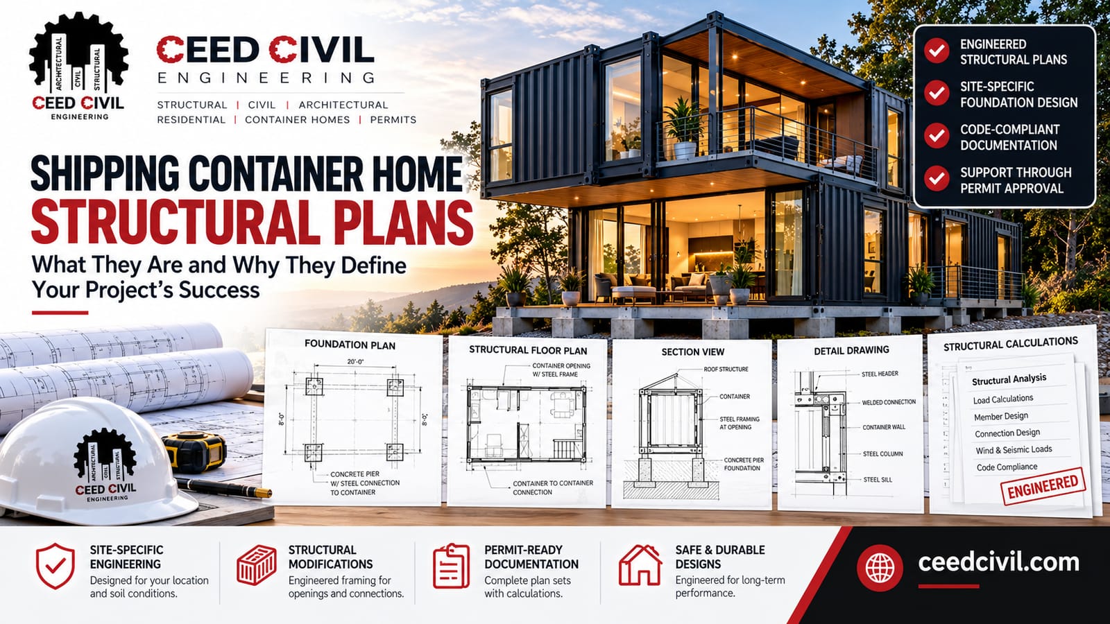
The connection detail between pier and container is one of the most important details in shipping container home structural plans. A common approach uses a steel base plate anchored to the top of the concrete pier, with connection hardware that interfaces with the container’s corner casting. The detail needs to be positive (providing resistance to uplift and lateral movement, not just bearing against gravity loads) and needs to allow minor field adjustment to accommodate the slight dimensional variations in the actual container positions relative to the theoretical pier locations.
Grade Beams: Connecting the Piers
Grade beams are concrete beams that connect adjacent piers, adding structural continuity to the isolated pier foundation system. Their use in shipping container home structural plans is appropriate in several situations.
For longer container configurations particularly end-to-end arrangements that create linear buildings where the distance between support points along the building’s length is significant grade beams connecting the piers along each side reduce the differential settlement risk between adjacent support points. A pier that settles slightly more than its neighbor produces differential settlement in the building above. A grade beam connecting the two piers distributes the settlement more evenly because the beam resists the differential displacement.
Grade beams also improve the lateral resistance of the foundation system. A foundation consisting of isolated piers resists lateral loads through the cantilever action of each pier in the soil. A foundation with grade beams connecting the piers acts more as a unified rigid frame, distributing lateral loads among all the piers rather than relying on each pier independently.
For sites with more variable soil conditions, where the bearing capacity varies across the building footprint, grade beams provide the load redistribution that helps the foundation system perform more uniformly despite the soil variability.
The Geotechnical Investigation That Foundation Design Requires
Every foundation design in shipping container home structural plans should be based on actual soil data from the specific project site rather than on assumed or typical soil properties. The geotechnical investigation that produces this data is a standard pre-design service that a geotechnical engineering firm provides.
The investigation typically involves drilling soil borings at representative locations within the building footprint. The boring locations and depths are specified to provide adequate site characterization for the proposed foundation system. For a simple single-container home on a compact site, two or three borings may be adequate. For a larger multi-container configuration or a site with visible evidence of variable soil conditions, more borings at more locations may be required.
Samples collected from the borings are tested in a laboratory for the properties that foundation design requires. Bearing capacity: the load per unit area the soil can support without shear failure. Compressibility: how much the soil will consolidate under sustained load, which determines the expected settlement. Plasticity: for clay soils, the degree to which the soil’s volume changes with moisture content, which affects whether the foundation needs to address expansive soil behavior.
The geotechnical report translates the boring and laboratory data into foundation design parameters. The allowable bearing pressure the soil can support. The estimated settlement under that pressure. Any special design requirements arising from the specific soil conditions. Foundation design that uses these project-specific parameters performs as calculated. Foundation design that uses assumed parameters performs as hoped.
Foundation Plans in the Permit Package
The foundation plan is typically the first structural drawing reviewed in a building permit submission for shipping container home structural plans. It establishes the building’s relationship to the ground and provides the basis for understanding every structural element above it.
A complete foundation plan shows the building footprint with dimensions. The location of every foundation element (every pier, every grade beam, every bearing pad) with dimensions establishing its position relative to the building footprint and to property lines. The size of every foundation element. The reinforcement of every element, shown in plan and referenced to section and detail drawings that show the reinforcement layout in three dimensions.
The connection details between foundation elements and containers are referenced from the foundation plan and shown in detail drawings at large enough scale to show the connection hardware, the weld or bolt details, and the dimensions required for fabrication and installation.
The foundation plan is accompanied by the geotechnical report and the foundation design calculations that demonstrate the adequacy of each foundation element for the loads it carries and the soil conditions it bears on.